Acrylic Case
Follow these instructions to complete your Zaphod assembly if you purchased the acrylic case kit.
Kit Content
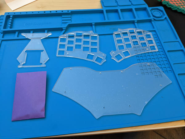
The Zaphod acrylic plate case kit contains the following:
| Qty | Name |
|---|---|
| 1 | Base plate |
| 2 | Switch plates |
| 1 | Top plate |
| 4 | m2 x 4mm knurled standoffs |
| 4 | m2 x 8mm knurled standoffs |
| 16 | m2 x 3mm screws |
| 16 | m2 x 6mm screws |
| 8 | bump-ons |
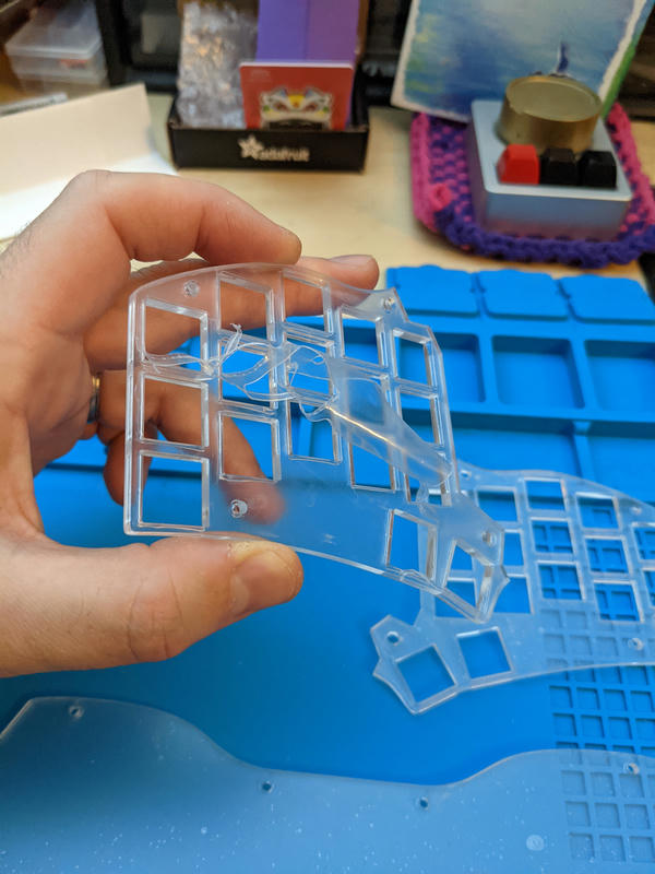
Remove Acrylic Protective Sheets
The acrylic sheets for your case arrive with a thin protective sheet adhered to the top and bottom surface of each plate to prevent accidental scratches. Before installing each plate, carefully remove the protective sheet from both sides first. These sheets should peel off fairly easily.
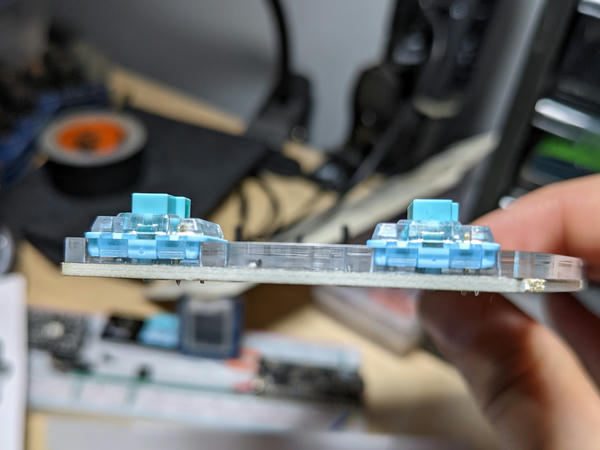
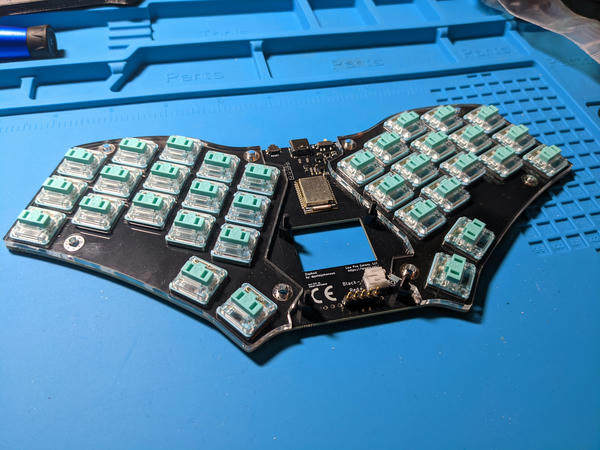
Switches and Switch Plates
First up: Install the switches with the left and right switch plates. The switch plates are designed to sit exactly flush with the top surface of the PCB -- the pre-soldered switch diodes are concealed within the Kailh Choc LED slot.
-
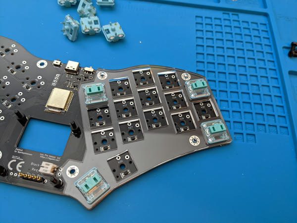
Select the first switch plate (they are interchangeable), and align the cutouts over the switch outlines on the surface of the PCB.
-
Insert switches in the four corner locations through the switch plate and into the PCB. The acrylic sheet should sit flush with the PCB, and the legs of the switches should be extending, if only partly, through the bottom of the PCB. Given the tolerance of the switch pin holes, you may need to apply slight pressure to ensure the switches are fully inserted.
-
Once aligned and held in place by the first four switches, insert the remainder of the switches, ensuring they are all fully inserted.
-
Next, flip the keyboard over and solder the two legs of every switch. Press each switch in one more time directly before soldering to be sure each is fully inserted. Consider soldering the first four corner switches first.
-
Repeat for the other side.
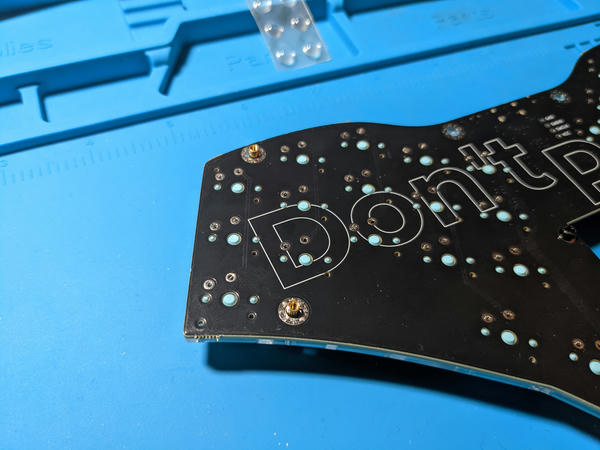
Short Outer Standoffs
With the switches soldered, you can now install the shorter 4mm standoffs on the switch plate in the mounting holes on the four outer corners of the keyboard.
-
Determine whether you need the 4mm or the 6mm M2 screws. Try the shorter 3mm first. Use to the longer 6mm only if the 4mm do not properly catch the thread and hold the standoff in place.
-
Place each screw through the top of switch plate and attach the standoff through the hole in the pcb.
-
Once all of the screws are in place, carefully tighten all four screws. Do not over tighten.
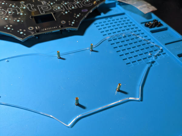
Tall Inner Standoffs
Put aside the top portion, e.g., the PCB and switches, and pick up the acrylic back plate and the 8mm standoffs.
- Again, determine whether you need the 3mm or 6mm M2 screws -- it should be the same length you used for the shorter standoffs.
- Attach the longer, 8mm standoffs to the four interior holes of the bottom plate.
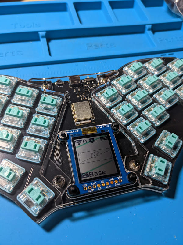
Install the Battery and Display
Follow the guides linked below. The display standoffs must be installed before you attach the back plate.
- Battery installation
- Display installation. This step is optional. The display is not required.
Attach the Bottom Plate
Time to put the top and bottom together.
- Carefully place the top portion face down (switch stems down).
- Line up the four long standoffs on the bottom plate with the interior mounting holes on the PCB.
- Lower the bottom plate until it rests on the shorter outer standoffs.
- Attach the bottom plate to the standoffs using the m2 screws. Again, try the shorter 4mm screws first and use the longer 6mm screws if you find the acrylic plate to be too thick.
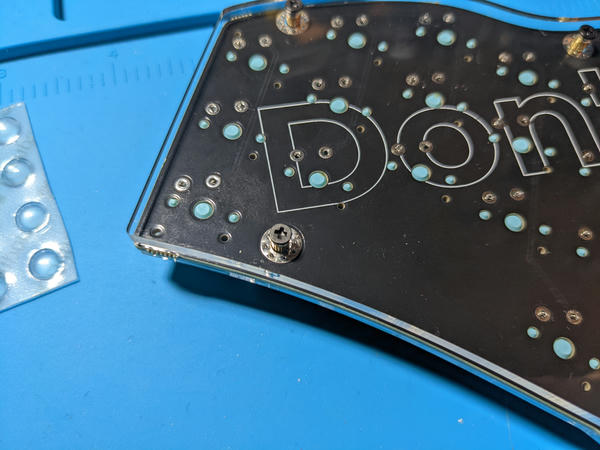
Add Bump-ons
Once the bottom plate is attached, it is time to install the bump-ons. Eight are included with the kit, but usually only six are needed.
-
Place one bump-on on each corner (4)
-
Place one bump-on horizontally centered along the top and bottom edge of the case (2)
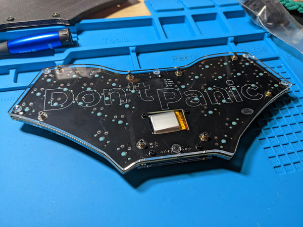
Install the Middle Acrylic Plate
Note: Before installing the final middle cover, follow the battery installation and the display installation guides.
- Ensure the keyboard is face up.
- Place the middle acrylic plate on top of the longer, inner standoffs.
- Attach the middle plate with either the 4mm or 6mm m2 screws.
Next Steps
You're nearly done! Add whatever keycaps you want to use and jump over to the typing test.