Switches
Follow these instructions install the switches for your Technikable
Assembly
The first step to assembling your Technikable is installing the switches, connecting the switch plate to the PCB.
Bottom Row Layouts:
Technikable supports three possible layouts for the middle section of the bottom row:
- Full ortho, all 1u keycaps.
- "MIT" layout, with one 2u keycap in the middle of the bottom row.
- "Dual 2U" layout, with two 2u keycaps sharing the middle of the bottom row.
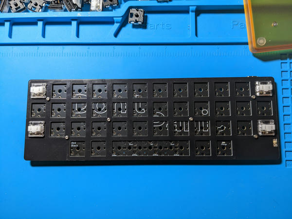
Before installing switches, decide on what layout you want to use, and make a note of the silk on the PCB indicating which switch locations to use depending on your choice:
TODO: Pic of the silk!
Polycarbonate (PC) Case Standoffs
To make the final assembly easier, if building with the polycarbonate Technik case, it is recommended to attach the standoffs to the switch plate first, before installing any switches.
-
Locate the standoffs, and pan-head (not countersunk/tapered) screws that came with the case.
-
Ensuring the standoffs are connected to the bottom of the switch plate, screw the standoffs to the switch plate, one for each drilled hole in the plate.
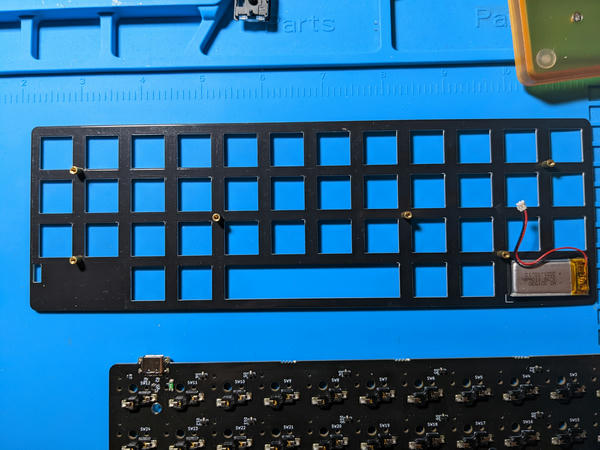
PCB
Before installing the switches, place the Technikable PCB face down on top of the face down switch plate. Verify the power switch is properly oriented to stick through the cutout in the switch plate. If using standoffs for the PC case, ensure all standoffs are properly inserted into the through holes in the PCB.
Switches
To make it easier to keep the switch plate properly separated from the PCB, it's recommended to install the switches closest to all the edges first, working your way towards the middle.
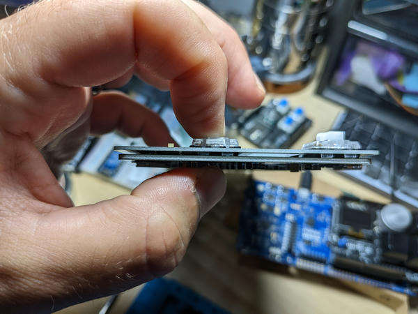
Technique
In order to ensure the longevity of your Technikable PCB and hotswap sockets, it's recommended to insert the switches by pressing the switch and socket between the thumb and index finger when inserting them, ensuring the hotswap sockets are not stressed/pushed awy from the PCB during insertion:
So the process for each switch is:
- Check that the two metal leaf pins of the switch are straight, not bent in any way.
- Align the switch with the switch plate opening, ensuring it is rotated the correct orientation.
- Pressing the switch with your index finger, and the socket from below with your thumb, squeeze the two together until the switch slides into the PCB fully.
- While still holding the switch in place, gently pull the switch plate up, to ensure the switch clicks into place within the switch opening, leaving a 1mm gap between the Technikable PCB and the switch plate.
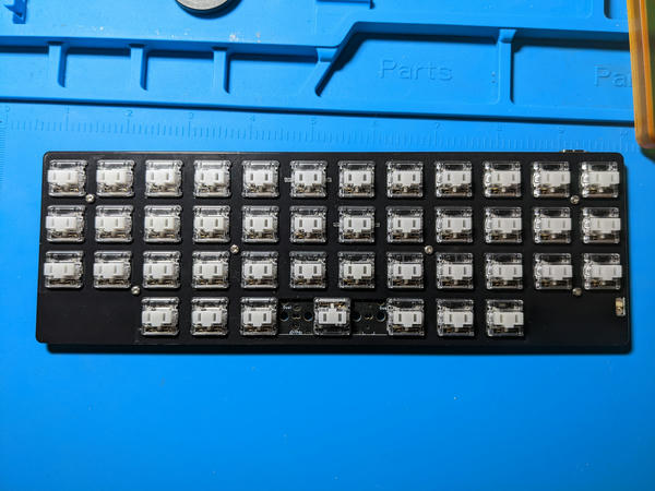
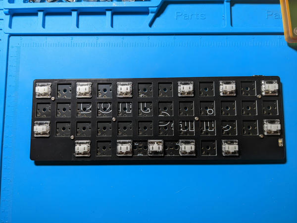
First Four Switches
Using the above technique, insert the first four switches into the four corners of the Technikable:
Bottom/Top Rows
Next, fill in some of the switches in the top and bottom rows. For any switches for the MIT or Dual 2u layouts that are for 2u keycaps, the switches will need to be rotated 180 degrees ("north facing") when installed into the alternate hotswap sockets:
Once complete, insert switches into the remaining gaps of the top/bottom rows, as well as the next row up:
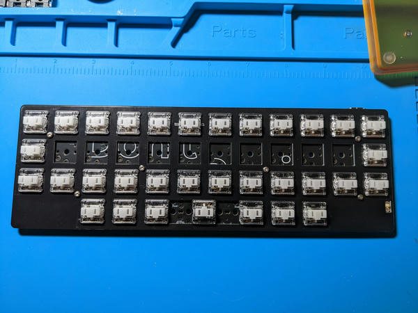
Remaining Switches
Next, insert the remaining switches: