Switches
Follow these instructions install the switches for your Blank Slate
Preface
A note: Due to the way the PCB battery cutout removes the PCB from under the corners of several switches, plateless builds are not possible with Blank Slate.
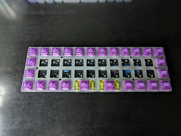
Also, when installing switches into Blank Slate, always verify the switch orientation, using the white hotswap socket openings as a visual guide. Blank Slate has a mix of north- and south-facing switches, in order to allow for the battery cutout, making it important to check the orientation carefully.
Bottom Row Layouts
Blank Slate supports three possible layouts for the middle section of the bottom row:
- Full ortho, all 1u keycaps.
- "MIT" layout, with one 2u keycap in the middle of the bottom row.
- "Dual 2U" layout, with two 2u keycaps sharing the middle of the bottom row.
Before installing switches, decide on what layout you want to use, and make a note of the silk on the PCB indicating which switch locations to use depending on your choice.
Stabilizers
If using a bottom row layout that includes any 2U switches, before installing any switches, be sure to install your stabilizers first. If you've never before used/installed stabilizers, it's worthwhile to review a guide on Identifying Stabilizer Tuning Issues to be sure your stabs function well.
As a reminder, although they can be made to work, screw in stabilizers have some physical interferance with the hotswap sockets on Blank Slate. As a result, clip in stabilizers are recommended instead.
Switches
To make it easier to keep the switch plate properly separated from the PCB, it's recommended to install the switches closest to all the edges first, working your way towards the middle.
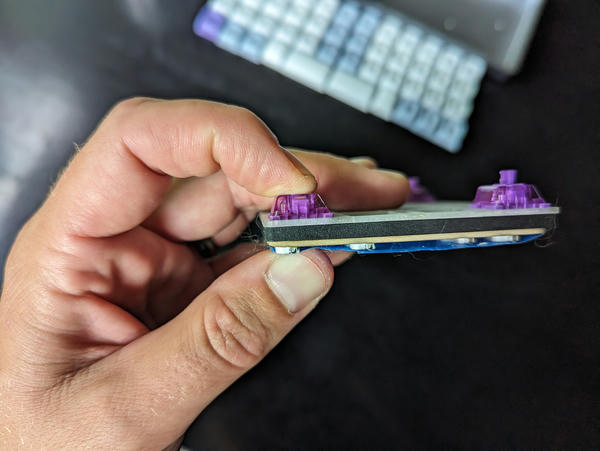
Technique
In order to ensure the longevity of your Blank Slate PCB and hotswap sockets, it's recommended to insert the switches by pressing the switch and socket between the thumb and index finger when inserting them, ensuring the hotswap sockets are not stressed/pushed awy from the PCB during insertion:
So the process for each switch is:
- Check that the two metal leaf pins of the switch are straight, not bent in any way.
- Align the switch with the switch plate opening, ensuring it is rotated the correct orientation. Remember that each row may have a different orientation than the one above or below it.
- Pressing the switch with your index finger, and the socket from below with your thumb, squeeze the two together until the switch slides into the PCB fully.
- While still holding the switch in place, gently pull the switch plate up, to ensure the switch clicks into place within the switch opening, leaving a 1mm gap between the Blank Slate PCB and the switch plate.
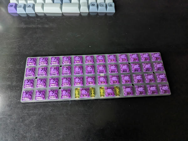
First Four Switches
Using the above technique, insert the first four switches into the four corners of the Blank Slate:
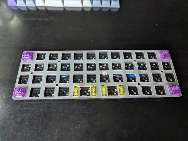
Bottom/Top Rows
Next, fill in some of the switches in the top and bottom rows. If using the full grid ortho bottom row, the center four switches will need to be rotated 180 degrees ("north facing") when installed into the alternate hotswap sockets:
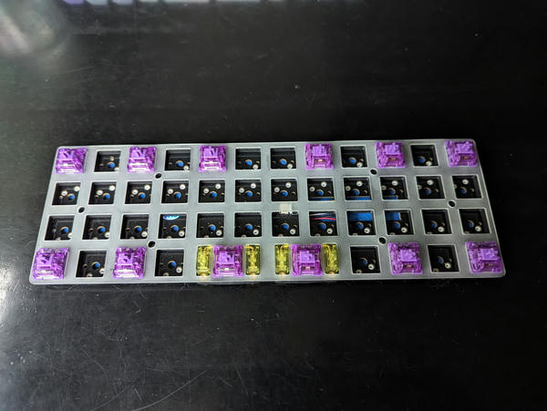
Once complete, insert switches into the remaining gaps of the top/bottom rows, as well as the next row up:
Remaining Switches
Next, insert the remaining switches: