Display
Zaphod is designed to work with the Adafruit Sharp Memory Display. The Zaphod display should be installed first, before any switch or case assembly.
Kit Contents
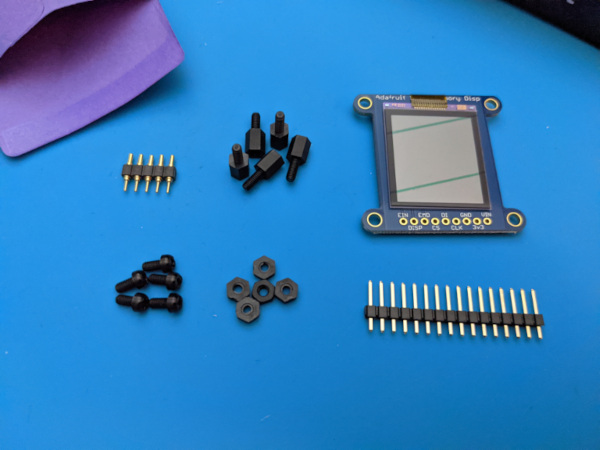
The display kit you purchased with your Zaphod includes the following items:
| Qty | Name | Sources |
|---|---|---|
| 1 | Adafruit Sharp Memory Display | adafruit, mouser |
| 1 | 1 x 5 Mill-Max Spring Loaded Header (825-22-005-10-001101) a.k.a. Pogo pins | mouser, digikey |
| 4 | m2.5 x 6mm male-female nylon standoff | aliexpress |
| 4 | m2.5 nylon nut | aliexpress |
| 4 | m2.5 x 6mm philips nylon pan head screws | aliexpress |
If you did not purchase the display kit with your Zaphod PCB, the parts can be purchased separately. The links provided are some options, but anything matching those specs will work.
Installation
First, attach the standoffs to the four mounting holes of the Zaphod PCB:
- Place a screw up through the bottom of the PCB
- Thread the female end of the standoff onto the screw
- Repeat for all four standoffs
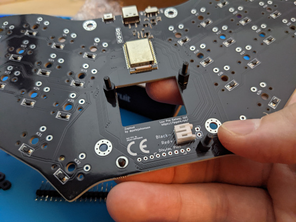
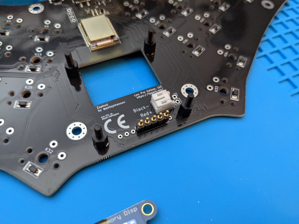
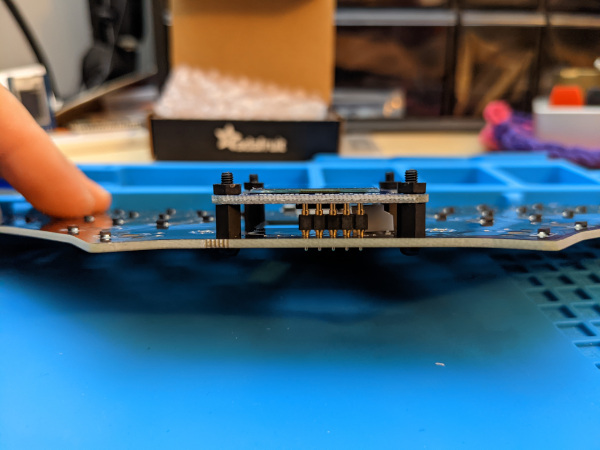
Next, insert the spring-loaded header into the Zaphod where indicated by the "Display Pins" label. Be sure to use the pins labeled "Display Pins" on the front silk. The extra pins are there for possible future alternative modules used with Zaphod. When correctly place, you will see three empty holes to the left of the spring-loaded header, and one empty hole to the right.
Note: the "springy" part of the spring-loaded header should be up, with the solid pins inserted into the Zaphod PCB.
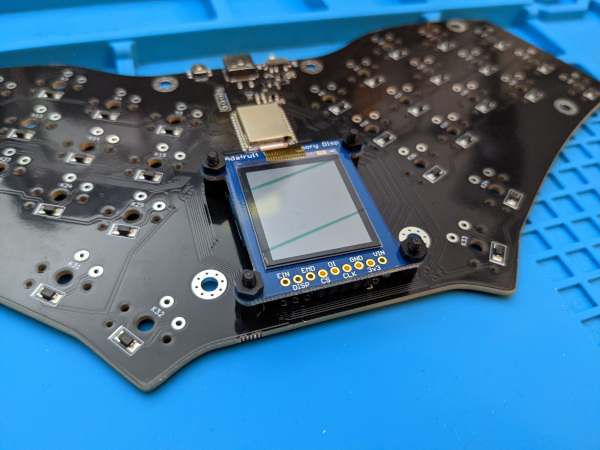
Before you solder the spring-loaded header to the Zaphod board, attach the display. This step will ensure the spring-loaded header is properly aligned during soldering:
- Gently place the display so the four holes on the corners slide over the male end of the standoff
- Make sure the spring-loaded header tips are properly aligned with the pin holes on the bottom of the display PCB
- Add four nuts on each mounting post, slowly tightening each corner to engage the spring-loaded header, and ensure everything is in place.
It is important that you verify the spring-loaded header alignment before soldering!
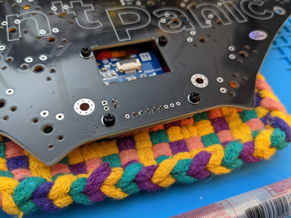
Once the display is fully tightened, flip over Zaphod and gently place the keyboard face down on a soft material that will protect the display.
Now you can solder the five pins of the spring-loaded header from the bottom.
Do NOT solder the spring-loaded header to the display PCB; these pins are designed to make a stable connection to the display without requiring soldering.
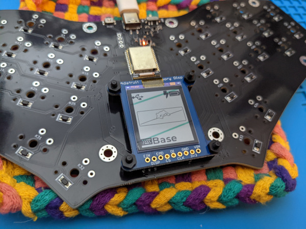
Testing
You should now be able to plug in a USB cable to keyboard and verify the display is working:
Next Steps
With the spring-loaded header properly soldered to the Zaphod PCB, unscrew the nuts and set the nuts and display aside until the rest of the assembly is complete. This will help ensure the display is not harmed during the remaining assembly steps.